This paper is available on arxiv under CC BY-NC-ND 4.0 DEED license.
Authors:
(1) Akash Chikhalikar, Graduate School of Engineering, Department of Robotics, Tohoku University;
(2) Ankit A. Ravankar, Graduate School of Engineering, Department of Robotics, Tohoku University;
(3) Jose Victorio Salazar Luces, Graduate School of Engineering, Department of Robotics, Tohoku University;
(4) Yasuhisa Hirata, Graduate School of Engineering, Department of Robotics, Tohoku University.
Table of Links
- Abstract & Introduction
- Related Work
- Semantic Mapping Framework
- Multi-Target Search
- Experimental Studies
- Conclusions and Discussions, Acknowledgment and References
III. SEMANTIC MAPPING FRAMEWORK
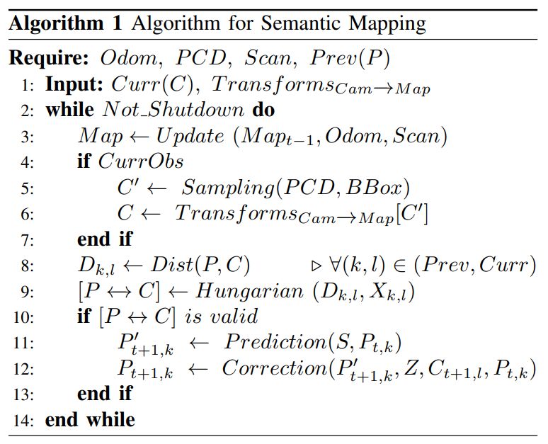
This section presents our semantic mapping framework, which builds upon our previously introduced framework [21] by adding additional layers to the semantic map and increasing the number of object classes. We begin with a brief description of the pre-processing steps followed by a detailed description of the second layer of our semantic map. This layer involves the integration of conventional SLAM processes with a filtering and tracking module, enabling the overlay of the grid map with object information. Finally, we compute an ‘observation layer’ based on the obtained object information. Similarly, several such layers can be added with new information in our framework such as map topology or region segmentation [22].
Our framework extensively utilizes the open-source middleware Robot Operating System (ROS [23] and its associated libraries. We use the ‘Grid Map Library’ [24] to build, visualize and maintain our triple-layered map in conjunction with ROS. Additionally, we utilized the Azure Kinect DK sensor SDK [25] in the design framework.
A. Pre-processing
The RGB and depth images from the Azure Kinect sensor are registered to prepare the semantic map. The depth image is registered in the RGB frame since the RGB image has a lower FoV (Field of View) and subsequently, the compressed depth and RGB images are transported from the onboard computing system to the server computer. These images are rectified using intrinsic camera calibration parameters provided by the SDK, and finally, the point cloud data is generated.
B. Mapping
The resulting point cloud data is used to create a 3D grid map (octomap) of the environment. While any kind of 3D map representation can be used for navigation such as RGBDSLAMv2 [26], we choose RTAB-Map [27] as the preferred method because of its appearance-based loop closure in real-time.
Five of the most ubiquitous object classes in indoor spaces, namely the chair, bed, table, TV, and sofa, are taken into consideration for generating the semantic map. During the mapping process, YOLOv7 [7] is employed to detect objects in frames. The YOLOv7 network generates a 5-D output for each detected object, including the object class and four bounding box parameters (centre coordinates: Cx and Cy, breadth: B, and length: L). The bounding boxes are randomly sampled and the mean X and Y coordinates are computed from the corresponding point cloud data. Multiple
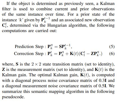
measurements over time are fused using Kalman filtering before placing 3D models on the map frame.
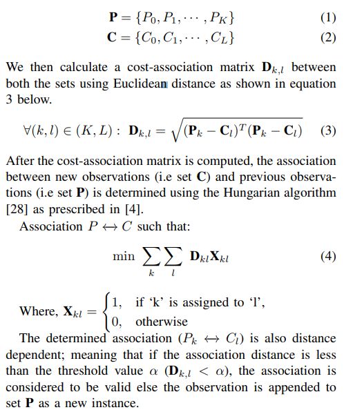
After an object is placed on the map, it needs to be tracked to determine if it is a previously detected instance of that object or not. For tracking the objects in these scenarios, we maintain the record of ′K′ previously seen objects of a class and current observations for latest frames (′L′ objects of the same class) as follows:
C. Observable Region Layer
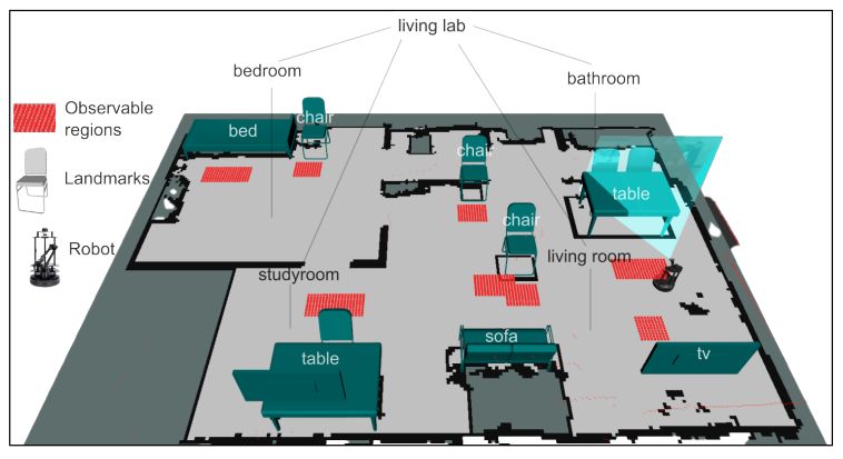
After completion of the mapping phase, we determine the observation regions. An observable region in our context is defined as an area around the landmark such as chair, from where it is sufficiently visible. We define a rectangular region based on the location of the landmark.
The Observable Region layer (refer Fig. 2) enables us to perform region-to-region navigation. When the robot explores ‘chair space’ to search for an object, it navigates to the associated region. Once the robot is within the region, the robot reorients itself to search for any target on the chair. Thus, a region-to-region navigation is established.
The purpose for defining observable regions is manifold. First, it reduces the time required and the cumulative distance traveled by the robot to find the object. Secondly, if the navigation goal is occluded due to an obstacle, the robot can still successfully navigate near the point and search for the target. In any case, the robot’s final pose is facing the desired landmark. Lastly, it eliminates the need to undertake oscillatory movements or recovery maneuvers due to erroneous planning or overshoots during execution.
